EMSphInxEBSD
EMSphInxEBSD is a GUI for indexing EBSD patterns using spherical harmonics, part of the EMSphInx package.
Main Window
The main window consists of a menu bar (top), live indexing result (left), indexing parameters (right), and progress/status bar (bottom). To index an EBSD scan first specify the parameters by editing the summary panel directly, loading a namelist file, and/or using the wizard (Menu ▶ File ▶ Wizard). Once the parameters are specified hit the ‘Start’ button and indexing will begin.
Indexer initialization may take several minutes on the first run as Fourier transforms are being planned. To preplan DFTs use Menu ▶ Tools ▶ Build Wisdom.
The main window is split into 3 primary sections as seen in the screenshot below: live indexing result (left), Parameter Summary Panel (right), and status bar (bottom)
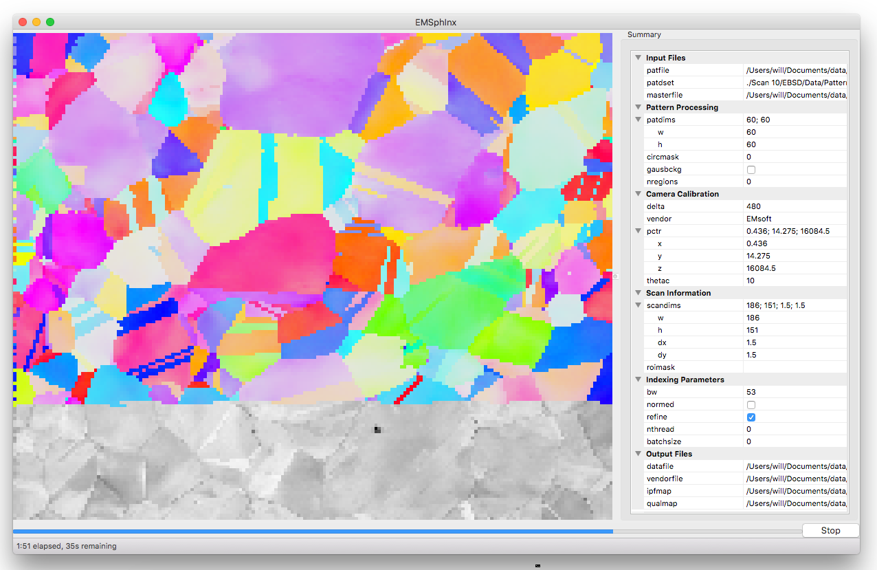
Parameter Summary Panel
The parameter summary panel is split into 6 sections detailed below:
- Input files - EBSD pattern source and simulated master pattern
- Pattern Processing - pattern size and image preprocessing
- Camera Calibration - detector geometry description
- Scan Information - orientation map dimensions and region of interest
- Indexing Parameters - spherical cross correlation and threading parameters
- Output Files - locations to save indexing results
If you are uncomfortable filling parameters directly, use the wizard.
Input Files
| Name | Type | Value |
| patfile | file | EBSD patterns to index (.up1, .up2, .ebsp, or .h5) |
| patdset | string | path to patterns within hdf5 file (ignored for other formats) |
| masterfile | file list | spherical master pattern files to index against (.sht), first file is phase 0 in output, second file is phase 1, etc. |
Pattern Processing
| Name | Type | Value |
| patdims.w | integer | width of detector in pixels |
| patdims.h | integer | height of detector in pixels |
| circmask | integer | circular mask radius (-1 for no mask, 0 for inscribed circle, >0 for radius in pixels) |
| gausbckg | boolean | should a 2D Gaussian background be subtracted from patterns |
| nregions | integer | number of tiles for adaptive histogram equalization (0 for no equalization) |
Camera Calibration
| Name | Type | Value |
| delta | real | detector pixel size in microns (i.e. patdims.w * delta is the width of the detector) |
| vendor | enum | pattern center convention (EMsoft, Bruker, EDAX, or Oxford) |
| pctr.x | real | pattern center calibration, see table below or refer to the EMsoft tutorial paper for details |
| pctr.y | real | |
| pctr.z | real | |
| theatc | real | camera elevation angle in degrees, refer to the EMsoft EBSD forward model paper for details |
Pattern Center Conventions:
| Name | EMsoft | Bruker | EDAX | Oxford |
| pctr.x | pixels | detector widths | detector widths | detector widths |
| pctr.y | pixels | detector widths | detector widths | detector heights |
| pctr.z | microns | detector heights | detector widths | detector widths |
| origin | center | top left | bottom left | bottom left |
Scan Information
| Name | Type | Value |
| scandims.w | integer | width of scan grid in pixels |
| scandims.h | integer | height of scan grid in pixels |
| scandims.dx | real | width of grid pixel in microns |
| scandims.dy | real | height of grid pixel in microns |
| roimask | string* | string representation of region of interest to index (or empty to index everything) |
The ROI string is a series of (x,y) image coordinates (integer pixels) with 3 shapes defined:
- Rectangle - first coordinate is origin, second coordinate is rectangle size
- Ellipse - ‘e’ + bounding box as rectangle
- Polygon - vertices in order (first/last point specified twice)
The region of interested can be inverted (the excluded region selected instead of the included region) by prepending the string with ‘i’. Here are some ROI string examples:
- only points inside the rectangle with corners at (12, 34) and (56, 79) - “12, 34, 44, 45”
- the same rectangle specified as a polygon - “12, 34, 12, 79, 56, 79, 56, 34, 12, 34”
- only points outside the circle with radius 50 and center (60, 70) - “ie10, 20, 100, 100”
If you’re uncomfortable manipulating the ROI string please use the wizard.
Indexing Parameters
| Name | Type | Value |
| bw | integer | Bandwidth to index with - time scales as bw3 * ln(bw3) so the lowest tolerable value should be used. The Euler angle grid size is (2 * bw - 1)3 so indexing is fastest when 2 * bw - 1 is a product of small primes. Slow sizes will be padded up to the nearest fast size so in practice most sizes are efficient. Here are some reasonable ideal sizes:
|
| normed | boolean | should normalized or unnormalized cross correlation be used for indexing - normalization is slightly slower but is suggested when pseudo-symmetry is anticipated or to index against multiple phases |
| refine | boolean | should newtons method refinement be used - slower but improves precision |
| nthread | integer | number of threads to index with (0 to determine from number of virtual cores) - performance peaks at ~1.5x the number of real cores |
| batchsize | integer | number of patterns to dispatch to a thread at once (0 to estimate a reasonable number based on bw) - extremely small values will incur additional threading overhead but large values make the ‘stop’ button take longer to work |
Output Files
| Name | Type | Value |
| datafile | file | location to write indexing results and meta data to (required) |
| vendorfile | file | optional location to write vendor file (.ang or .ctf) |
| ipfmap | file | optional location to write Z reference IPF map (.png) |
| qualmap | file | optional location to write (normalized) spherical cross correlation map (.png) |
Parameter Wizard
The EBSD namelist generation wizard has 6 panels to interactively fill the required parameters for indexing:
- Experimental Pattern Selection
- Master Pattern Selection
- Detector Geometry
- Scan Geometry
- Indexing Parameters
- Summary
Any error messages are displayed in the status bar (bottom left)
Experimental Pattern Selection
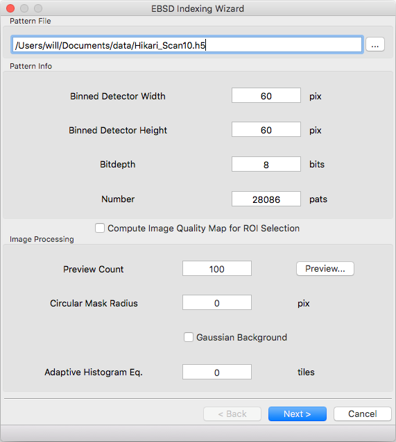
Pattern File
File to read EBSD patterns from. HDF5 (.h5, .hdf, .hdf5), EDAX (.up1, .up2), Oxford (.ebsp), and EMsoft (.data) files are supported. The pattern dimensions, bitdepth, and number of patterns will be determined automatically for all files except EMsoft raw files. Additional meta data will be parsed depending on file type
- HDF5 EBSD scan files
- EDAX files when there is a .ang with the same path/name
- Oxford files when there is a .ctf with the same path/name
The following additional metadata will be read and prepopulated if possible:
- pattern center calibration
- detector tilt
- scan dimensions
- scan pixel size
- Pattern quality and indexing confidence maps (for ROI selection)
Pattern Info
Detector geometry will be automatically determined for most file formats. Raw binary files require specifying the pattern size.
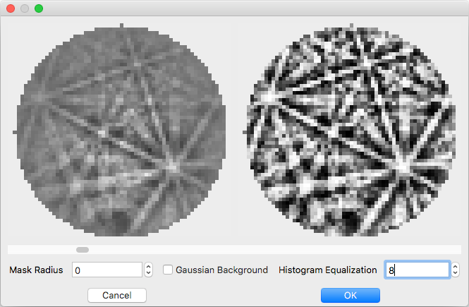
Image Processing
The easiest way to select parameters is with the ‘Preview…’ button. When the button is clicked ‘Preview Count’ evenly spaced patterns will be read from the file. The raw pattern is displayed on the left and the processed pattern on the right. Change which pattern is displayed with the scroll bar and adjust parameter values below. If the dialog is closed with the ‘OK’ button the current values will be populated into the wizard, otherwise they will be discarded.
If your pattern file doesn’t have associated maps for ROI selection you can tick the ‘Compute Image Quality Map for ROI Selection’ box to calculate IQ during pattern loading. If the box is ticked a computed IQ map will be available on the ‘Scan Geometry’ page.
Master Pattern Selection
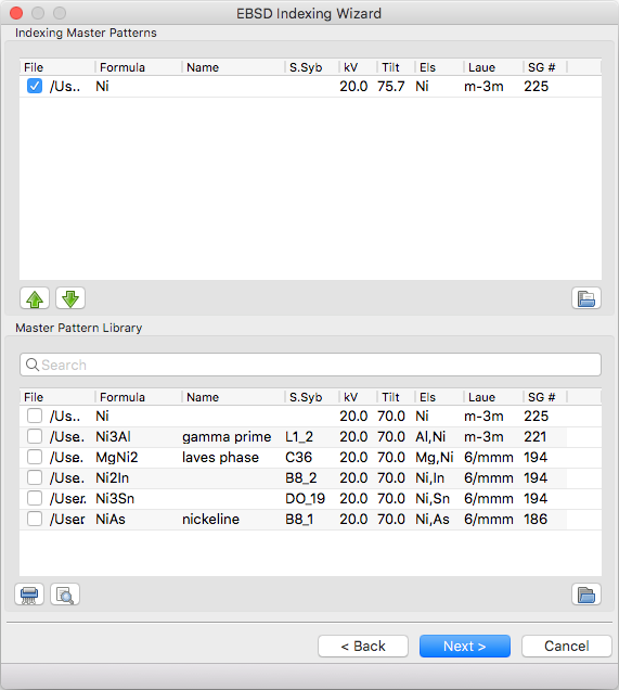
Indexing Master Patterns
Spherical master patterns to index against. Multiple patterns can be selected for multi-phase indexing. The first pattern in the list is phase 0, the second phase 1, etc. Use the up/down arrow buttons (bottom left) to reorder patterns. Click the file brows button (bottom right) to browse for a single master pattern file (.sht) to add to the indexing list. Master patterns can be removed from the list by unticking the checkbox (OS X or Linux only) or double clicking.
Master Pattern Library
All previously used master patterns that aren’t currently in the ‘Indexing Master Patterns’ box are listed here. Master patterns can be sorted by clicking on the column headers:
- File - full path the master pattern file
- Formula - material formula string
- Name - material/phase name
- S.Syb - structure symbol
- kV - accelerating voltage
- Tilt - sample tilt (degrees)
- Laue - crystal Laue group
- SG# - space group number (effective for overlap patterns)
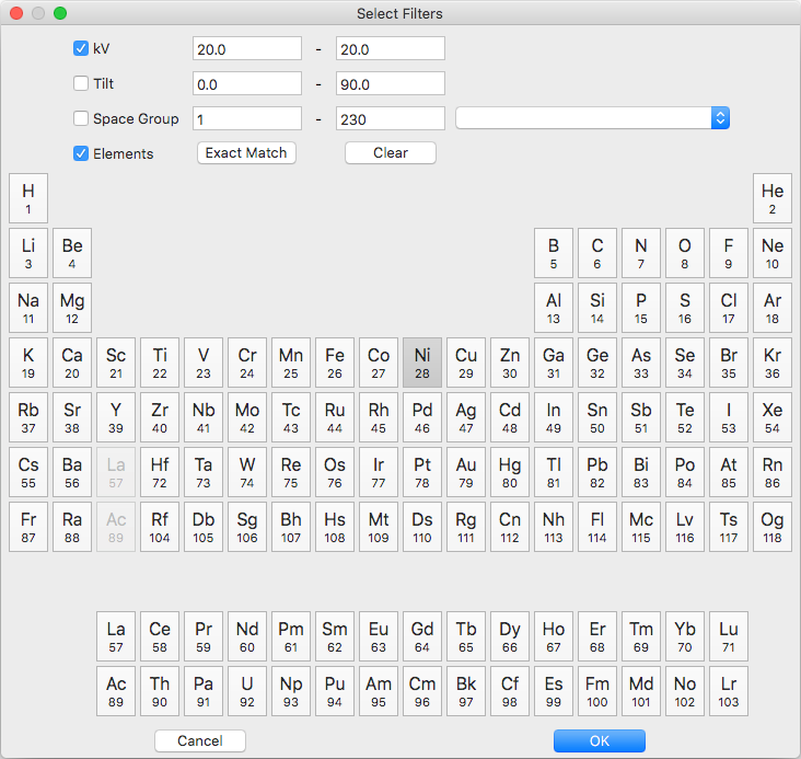
Known master patterns can be permanently removed from the list by selecting and then pressing the delete button (bottom left). Displayed master patterns can be filtered by file, formula, name, or s.syb with the search bar (top). Use the search button (bottom left) to filter by kV, Tilt, SG#, and/or composition. All master pattern files in a folder (recursive) can be added with the directory browse button (bottom right). Master patterns can be move to the indexing list by ticking the checkbox (OS X or Linux only) or double clicking.
Detector Geometry
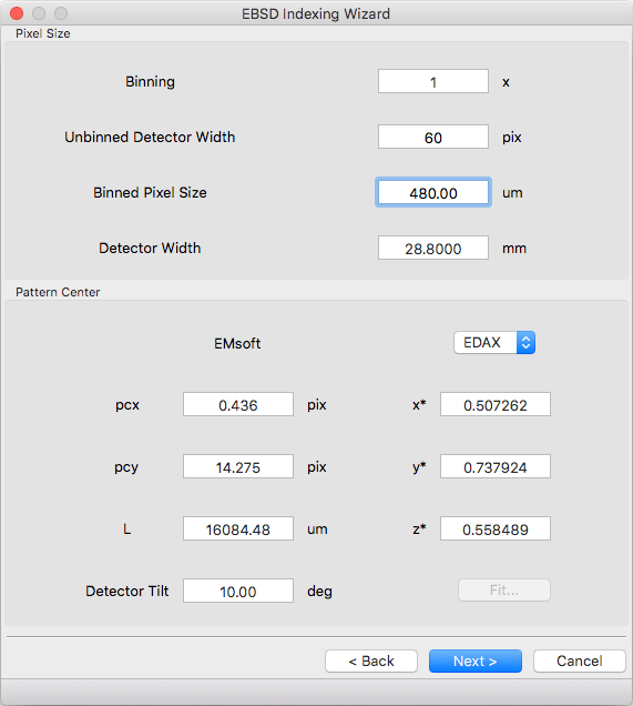
Pixel Size
Indexing requires the effective pixel size of the EBSD patterns in microns. Most scintillator based detectors have a pixel size of 50-100 microns. However if the detector is binned the effective pixel size increases by the binning factor. The unbinned detector width is read only and specified in pixels (it is the size from the Experimental Pattern Selection page). Consider a 640x480 detector with 50 micron pixels used to collect patterns with 4x4 binning:
- The pattern size is 160x120
- The effective pixel size is 200 microns (50 * 4)
- The detector width is 32 mm or 32000 microns (640 * 50 == 160 * 200)
‘Binned Pixel Size’ is the effective pixel size assuming the patterns were collected using ‘Binning’ x ‘Binning’ camera binning. Assuming that ‘Binning’, ‘Binned Pixel Size’, and ‘Detector Width’ are specified, then changing one will update the others accordingly:
- If ‘Binning’ is changed ‘Binned Pixel Size’ will be updated to keep ‘Detector Width’ constant
- If ‘Binned Pixel Size’ is changed ‘Detector Width’ will be updated using the current ‘Binning’
- If ‘Detector Width’ is changed ‘Binned Pixel Size’ will be updated using the current ‘Binning’
For the above example, the following combinations are all valid. Binning == 1 uses the effective experimental parameters, binning == 4 allows specifying the true pixel size, and other values are mathematically equivalent:
| Binning | Unbinned Detector Width | Binned Pixel Size | Detector Width |
| 1 | 160 pixels | 200 um | 32 mm |
| 2 | 320 pixels | 100 um | 32 mm |
| 4 | 640 pixels | 50 um | 32 mm |
| 8 | 1280 pixels | 25 um | 32 mm |
Pattern Center
The EMsoft pattern center is computed from the normalized pattern center using the binned pattern dimensions and pixel size. If the vendor dropdown is changed the normalized pattern center will be computed from the EMsoft pattern center using the current pixel size. The “Fit…” button is currently disabled but will be used for pattern center refinement in the future. Please refer to the EMsoft tutorial paper for details on pattern center and the EMsoft EBSD forward model paper details on the geometric model.
Scan Geometry
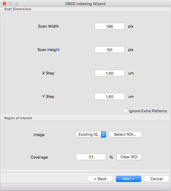
Scan Dimensions
Specify the number or columns / rows in the EBSD map scan grid and the grid pixel size in microns
Region of Interest
A region of interest (ROI) can be used to restrict indexing to a subset of the scan. ROI building requires a grayscale map either computed or loaded during experimental pattern selection. The percentage of pixel contained in the ROI is displayed in the coverage box and the ROI can be removed (index everything) with the clear button. To draw an ROI interactively click the ‘Select ROI…’ button.
ROI Drawing Dialog
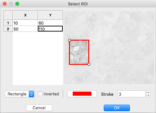
Select the ROI shape from the dropdown and draw a region accordingly. Pixels to index are unmodified and pixels to skip are grayed. Tick the inverted box to draw an exclusion region instead of an inclusion region. An existing ROI can be adjusted by clicking + dragging on a handle to change the shape or inside the selection to translate. If fine control on ROI positioning is needed the coordinates can be edited directly on the left.
- Rectangle - click on origin + drag to extend (hold shift during drag for square)
- Ellipse - click on bounding box origin + drag to extend (hold shift during drag for circle)
- Polygon - click to start
- During construction
- click to start / add a new point
- hold shift to snap line to horizontal or vertical
- press delete to remove the most recent point
- right click to close shape
- After construction
- right click on a point to remove it
- double click on a point to duplicate it (inserted after point)
- During construction
Indexing Parameters
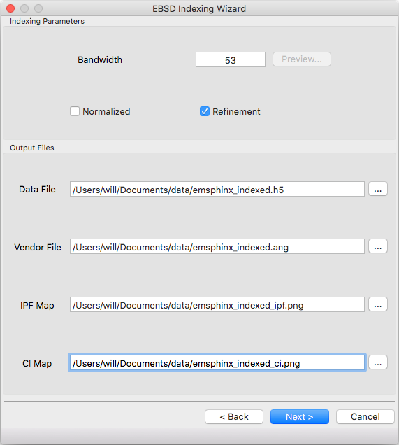
Specify the bandwidth, if normalize/unnormalized cross correlation should be used, and if newton’s method based refinement should be used.
Bandwidth
Indexing bandwidth, refer to the Indexing Parameters section of the Parameter Summary Panel documentation for details.
Normalization
Using normalized spherical cross correlation is slightly slower but is suggested when pseudo-symmetry is anticipated or to index against multiple phases.
Refinement
Newtons method refinement add some overhead but gives maximum orientation precision. If refinement is unticked then a sub-pixel maximum will be interpolated from the 3x3x3 box surrounding the maximum in the Euler angle grid.
Output Files
An output data file is required and contains the indexing results as well as all parameter metadata. A vendor file (ang or ctf) can be optionally generated to help import results into other software packages. Finally IPF (z reference) and spherical cross correlation maps (png) can be optionally generated.
Summary
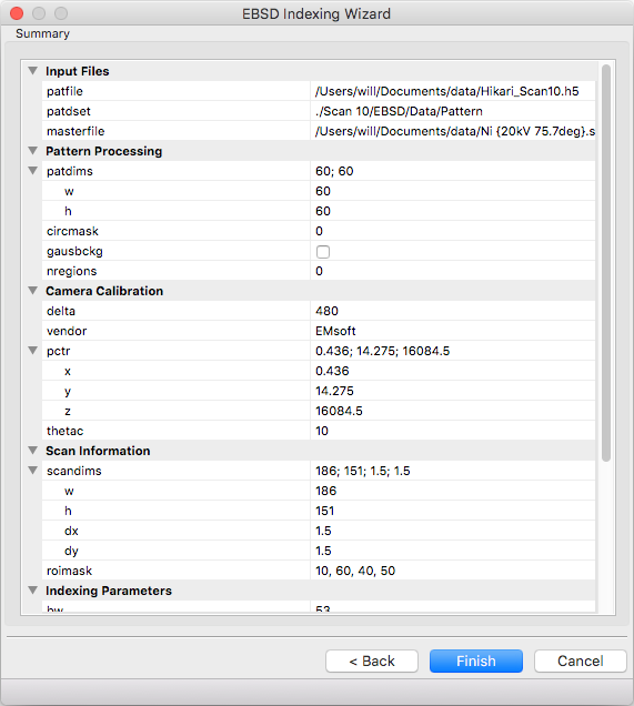
A read only summary of the generated parameters is displayed. Refer to the Parameter Summary Panel for details.
Example Data
The full 10 scan sequence used in the indexing paper can be downloaded here. The entire sequence is ~600 MB, a smaller file (~80 MB) containing only scan 10 is also available. A nickel master pattern corresponding to the scan conditions is in the github repo
Reasonable selections to walk through wizard for this dataset (only non-default values listed):
- Experimental Pattern Selection - Pattern File: HikariNiSequence.h5 - Scan 10
- Master Pattern Selection
- Indexing Master Patterns: Ni {20kV 75.7deg}.sht
- Detector Geometry
- Binning: 1
- Binned Pixel Size: 475
- Scan Geometry (no changes)
- Indexing Parameters
- Bandwidth: 53
- Refinement: ☑
- Summary (read only)